— Thomas M. Tuerke
 One of my favorite templates has turned out to be one to make dual-gauge switches. With it, you can of course build both left- and right-handed dual-gauge switches, but also left- and right-handed standard-gauge switches and left- and right-handed narrow-gauge switches as well—a worthwhile investment considering the cost of commercially-available dual-gauge switches, but the fact that it's such a multi-tasker is great, too.
But one thing I've always wondered is how do the two gauges go their separate ways? Dual-gauge track is expensive in the real world, and a single railroad seldom would have two gauges except by reason of acquisition. So, in theory, you're not going to have the entire system dual gauge, only some vital interchange right-of-way.
I mean, sure, you could (a) have each end of the dual-gauge trackage simply transition to one or the other gauge or (b) build a switch where the diverging route was one gauge, and the main route was the other. The problem with the second choice is one of maintenance: you've got moving track you have to point in the right direction. Plus, you've got not one, but three frogs in that contraption. Depending on how you build it, that's two frogs not being used—money badly spent. Considering that most railroads were notorious for cutting corners and cutting costs, this seems unlikely.
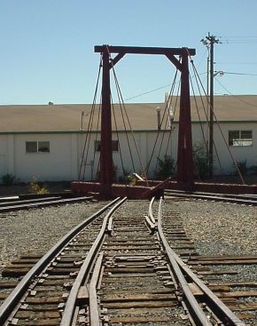
One possible solution—one I quickly point out may not be prototypical (or is it?)—is to build a "pointless" switch, in which one gauge permanently diverges, and the other permanently goes straight. The issue is the common rail: how do you govern that?
It turns out that traction has a "single point switch", which as the name suggests, has only one point. That point acts both as a point (when set for the main route) or as a guard rail (when set for the diverging route.) The place where the other point would be is simply shallow, and a wheel passing over that track simply rolls on its flange until it rides up onto the diverging rail again.
In my case, the fact that the different gauges determine whether the diverging or main route is taken means there's not even a need for a moving point; all that's really needed is a guard rail to pull the diverging wheelset off the main rail and onto the diverging one. A pointless "switch."
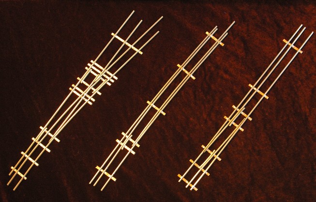
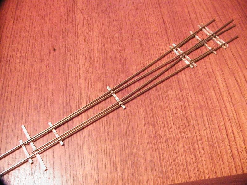
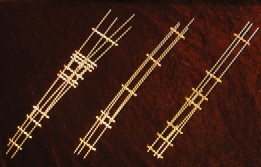 The cool thing is, the dual-gauge template is perfect for assembling this, and the combinations are numerous: you can have the standard gauge diverge and narrow go straight, or vice versa, and you can do so to the left or right direction. I've built several of these, and they work quite nicely. The photo here shows three "pointless exercises" from left to right: a pointless switch, a dual-gauge turntable approach, and a left-side to right-side transition.
Now, if you wanted to get really carried away, you could build a single-gauge switch inside of a chunk of dual-gauge track. For example, the throat of a small yard might be dual-gauge, but the ladder is only for the standard gauge; the narrow gauge might only have access to a single track (say, the team track.) That's not exactly pointless (that is, you would have two points,) but again, the dual-gauge seems like it would be the basis for such a project.
Like I said, quite a multi-tasker. I'm really liking this.
— Thomas M. Tuerke
As I mentioned, creating a switch using the templates isn't too hard, and even the first one or two turned out reasonably well. They were good learning exercises, even if I'd never put them on the layout: the frogs work, and everything is in gauge, but the points are pretty sorry. (I've gotten better since then.)
 Then it occurred to me: since the points are no good, why not see what it takes to turn the switches into stub switches? Stub switches are an older style of switch—perfect for the period I'm in the process of modelling—with no points like "modern" switches. Instead, the track leading up to the switch is pushed to one side or the other, lining up with one route or the other.
 It turns out this is a pretty straight-forward thing to do. With two otherwise unusable switches to experiment on (and possibly salvage) it's a fun experiment. And while the technique is based on chopping apart a finished switch, I'll look into what it takes to build one directly from the template.
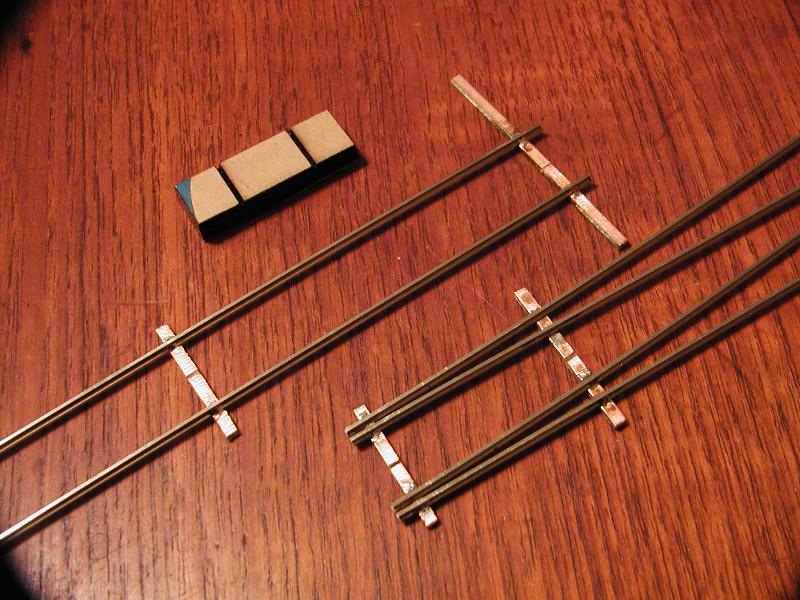
I started by identifying how far up from the base of the switch I had to go before the two routes diverged enough so both could be "in gauge" but that the there was enough flange-way between them. Once I found out where this would be, I soldered a PC tie, fastening the two stock (outer) rails and leaving the closure (inner) rails free to float. I wasn't concerned about the precise placement of this tie, but if you want to use a tie template, that's an option.
Next, I got out my trusty Mark-V and soldered one of the closure rails to the tie, making sure that (a) it was in-gauge, and (b) there was enough room between it and the outer rail for a flange to pass between them.
 Once I convinced myself that everything was to-spec, I did the same for the other closure rail. I then nipped the base of the switch and filed the ends of all four rails flat.
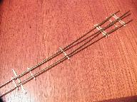
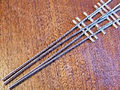
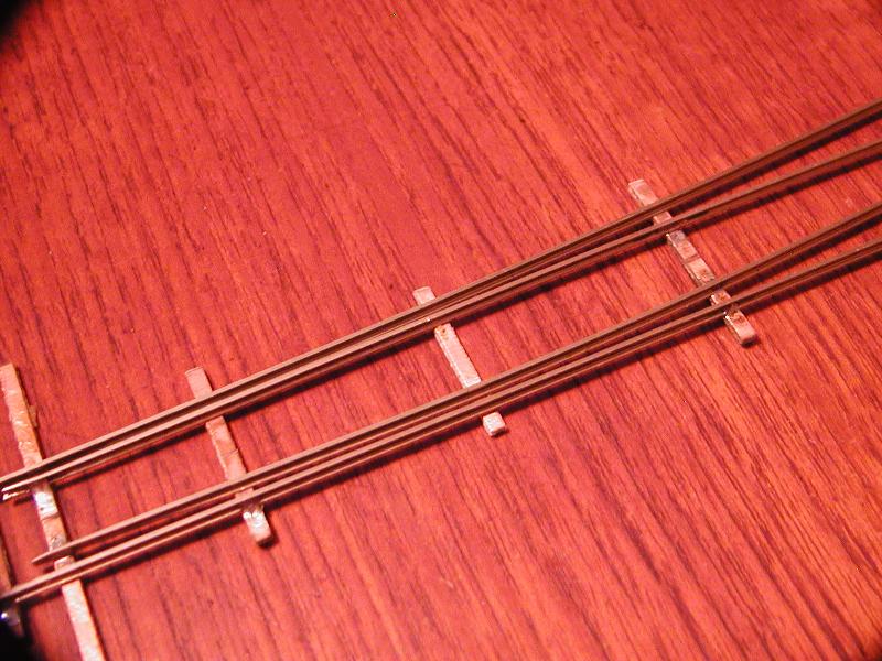
Finally, I cut a pair of lengths of rail to form the bending base of the stub switch. With the aid of some spacers to hold the rail in gauge, I soldered a long throw-bar PC tie at one end, a normal PC tie at the other end, and another tie about one third of the way, closer to the normal PC tie. This allows a reasonable amount of flexing between the throwbar tie and the middle one—even with code-70 rail—while allowing the other end of the rails to be firmly mounted to the roadbed. The rails between the throwbar tie and the middle PC tie will float; they won't be glued or spiked down, in order to allow them to move freely.
 Then I had to figure out a means of limiting the bending track to exactly line up with either one route or the other... I'm sure the ground throw would offer far too much motion from one extreme to the other, and the rails wouldn't align unless they were constrained somehow. My original idea was to cut small bits of brass to solder to the outside of the two outer rails. After some more consideration, I thought a rail joiner fastened to the end of the outer rails might do, if the insides of the joiner were removed. This seems to do acceptably well, but looked a bit unusual; I don't ever recall seeing such on protypical track, and it was too glaringly obvious. At the moment I've abandoned the idea of the limits soldered onto the track itself. Instead, I'll rely on spikes placed at the ends of movement of the throwbar PC tie to limit motion. If I'm not happy with that, I may just solder very fine piano wire to the outsides of the stock rails... a bit less visible than the brass, but probably just as effective.
Electrically, there's not much different from a standard switch, except that a pair of electrical leads will need to connect all the left-hand rails and right-hand rails, respectively. The frog will need to be gapped just like a normal switch, and powered by an electrical switch driven by the ground throw (or whatever is used to bend the track.)
On the whole, I'm fairly happy with the results. Rolling stock seems to negotiate the switch fairly well. I'm still in the process of mounting the first stub switch on a "permanent" base, to see how it behaves, but things look promising so far. Stay tuned!
Sections: 2
RE: Using the Templates to Create Stubs
— Thomas M. Tuerke
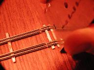
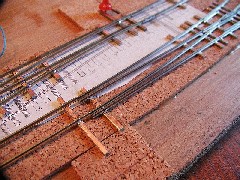
Well, one free afternoon later, and I've mounted the stub switch onto a bit of scrap plywood and cork. I hand laid some home-cut ties using a printed template for guidance, and used some "super glue" to hold the PC ties to the cork. (For proper mounting, I'd use pliobond or contact cement, but for this the CA glue should do fine.)
Mechanically, the track still works well. I noticed that one of the ground throws I have has a range far greater than the movement needed to switch the track... about twice as much; if this were a three way stub, the thing would be perfect, but here, I can only move it from one extreme to mid-way.
When gluing things down, I laid the flexible base to align with the main route when no pressure is applied to the throwbar, reasoning that I could use the half range of movement to push the throwbar—and thus the rails—to line up with the diverting route. In theory this works fine; in practice, there's enough friction between the base of the rail and the wooden ties to prevent the rail from returning to the normal main-route position. The ground throw will have to be linked to the throwbar by a pin or such; it won't just be able to push and retract, letting the rails spring back to normal.
(By the way, there's a small nail on the diverging-route side of the throwbar that prevents it from moving too far; this effectively limits the range of motion to line up perfectly with the diverging route.)
Rolling stock and the few engines I tried still negotiate the switch just fine, but I don't think going through a stub switch fast is a good idea. Unlike modern switches, unless the switch is thrown your way, derailment is almost a certainty. I imagine that this was the case around prototypical stub switches, too. I can envision all sorts of protocols involving creeping up to the switch, making sure it's thrown correctly, then "tiptoeing" over it until the train clears the switch.
The search is on for a better ground throw. The fine teeth of the delrin gear there now seems too weak to do the job; my guess is that this ground throw's days are numbered... but it sure looks nice.
I still want to try making a stub directly from the template; I'll have to be creative, because there's no pocket for the extra PC board tie that's needed. It looks like somebody ordering templates for the first time can request that as a feature—at least for some switch templates—and somebody making a grunch of them might find that useful. Back when I ordered, that wasn't an option. That's fine; I like improvisational challenges like that.
RE: Using the Templates to Create Stubs
— Thomas M. Tuerke
 Previously, I wanted to see what's involved in making a stub switch from one of the templates, as opposed to cutting up a reject.
Stub switches, it turns out, are quite easy to manufacture from the jig. Really, all you need to do is create the frog plus the stock rails. The closure rails don't need to be ground to points, but can be left square; they'll be cut to the desired length, along with the stock rails, once the switch is on site. During building, just make the stock and closure rails long enough to be able to rest in their grooves without interfering with the stock rails—just about where the closure rail needs to be ground to form the point.
Unlike conventional "point" switches, stub switches are two separate pieces, where the leading track is deflected to one of the two routes, rather than pointed closure rails forcing the train one way or another. This means that it's easier to finish the switch in its final location than in the template.
 The only tricky work—which is just a minor bit of fiddling—is bringing the four rails together, which we'll do after we make the flexing lead track. Here's how. This is slightly unconventional but seems to work well.
- Cut two strips of rail at least 4 inches long, preferably longer.
- Polish up one long "throwbar" tie and put it in the throwbar pocket of the template. Take two additional normal-length ties and put them into various pockets starting at least two, preferably 3, inches away from the throwbar tie. There won't be any PC-board ties in this 2-3 inch gap, as this stiffens the rails too much, and they won't flex.
- Lay the rails into the main route grooves so they rest on the ties you've inserted, with about one and a half ties worth of rail sticking over beyond the throwbar tie. You're really just using the template to make a bit of straight track with a throwbar at one end, and a couple of PC ties at the other. Note that since you're making the track "backwards" from its eventual orientation, the throwbar tie should be pointing to the "wrong" side of the track. Later, you'll remove the track and turn it 180 degrees about, and the tie will be on the correct side of the switch.
- File the ends of the track by the throwbar square and even.
- Place the lead track and your incomplete stub into their eventual destination, and secure things temporarily. (I use push-pins.) You'll have a bit of overlap between the two halves of the switch, which is a good thing for now.
- Mount the ground throw so that the lead track is relaxed when in the main route position.
- Now that you have the leading track and the almost complete stub, you have only to solder the four rails to a final PC-board tie. Solder the main stock rail, and the opposite closure rail so they are in gauge and in line with the leading track in its relaxed, undeflected state.
- Throw the ground throw so the lead track is flexed to the diverting route.
- Solder the remaining two tracks to the PC-board tie to be in gauge and aligned with the leading track in its flexed position. We do things this way, since each ground throw has a different amount of deflection, and this ensures that the amount of deflection is "just right" for the switch... by making the switch just right for the throw.
- Cut and file the four rails to meet up with the leading track. There should be a minimum of gap between the two halves. You'll be mounting the lead track at the "other" end of the flex, so expansion should be relatively minimal.
One final note: when wiring the frog, the contacts are "reversed" with respect to normal switches. That's because we're pulling or pushing the lead rail rather than the closure rails. Pushing/pulling the ground throw has the opposite effect (selecting main vs diverging route) as compared to normal switches. (You'll remember this the first time you run some motive power over the frog and it stops on you... ;-)
Making a 3-way stub switch is similar to this, only you'll build everything down to six rails (four closure, two stock) coming to a single location.) If you're using a hand-thrown ground throw, it should be installed so that the un-flexed/relaxed lead track is at the center of the ground throw's movement. The two diverging routes are then soldered at the place where the flexed lead track is located when at the extremes of movement in one direction or the other.


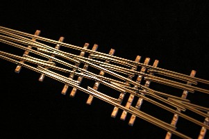
 I've been intrigued by the thought of hand-laying track, but thought spiking was tedious and prone to maintenance, and constructing a hand-made switch was an exercise in fiddly frustration. When I read about the Mojave & Panamint RR using rails soldered to printed-circuit ties, the idea really appealed to me. I did some research and found somebody that was selling switch templates to make precise hand-crafted turnouts.


 Generate a QR code link to this page