A set of module standards based on, and plug-compatible with, official T-Trak modules.
Background
In a recent trip to Japan, I got hooked on much of the passenger rolling stock and motive power of Japan Rail.
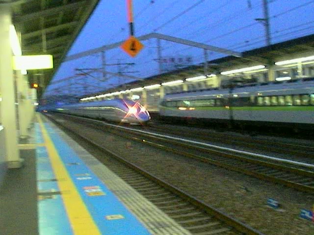
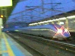 |
| A 500-series "Nozomi" slams by at 180 miles per hour! |
Compared to the stuff trundling on US rails, this stuff looks cool... especially the Shinkansen —bullet trains by another name. Some people get all excited about Ferraris and the like, but until you've had a quarter mile of sleek steel, aluminum, and glass slam by you a mere dozen feet away, you haven't felt excitement. (Okay, so that's my opinion, anyway. ;-)
Being the rail-fan that I am, I wanted to see if I could bring home some souvenirs. I model in HO, so I was rather disappointed to find out that there's not much available in ol' 1:87.1 in Japan. But model railroading is alive and well: it's just at one-hundred-sixty-to-one. N scale.
So I stuck my head in on Tenshodo and picked up some Shinkansen trains while I was there. I figured I could decide how to run them later, once I was home.
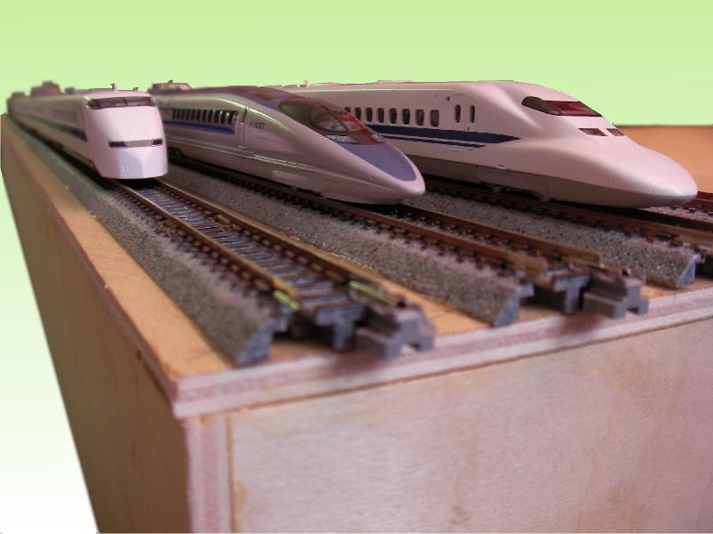
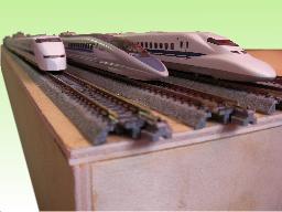 |
| Beautiful 1:160 scale models of the 300, 500, and 700 series Super Express trainsets |
Like I said, I'm an HO sorta guy, but I thought it sure would be nice to see these little beauties (and they are exquisitely modeled by KATO and Tomix!) run... preferably on something more than temporary flex track laid out on the floor or a table. The quest was on.
I've known about N-Trak for decades. It's where N-scale modelers build 2x4 foot portable modules (as opposed to full layouts) and join them together to run trains at meets. For me, these were (1) too big, and (2) wouldn't allow me to run trains when I wanted to.
Hmmm... a shelf layout, maybe... ?
About T-Trak
In my wanderings, I stumbled upon T-Trak, a system with modules about the width and depth of a piece of paper. A series of these could easily fit on a shelf. And in scale terms, that's about 110 x 160 feet. Not huge, but still enough to provide some scenery. Sort of like a slender "core sample" of the world adjacent to the right-of-way.
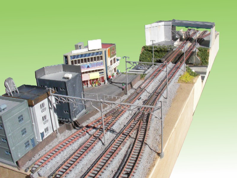
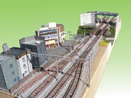 |
| Three modules - a "core sample" of track-side scenery |
What I Like About T-Trak
The form factor—the size and shape of these mini modules—is exactly what I'm looking for. They're also quite simple to construct with just quarter-inch plywood. The fact that it's based on KATO UNITRACK, while expensive, means that it's easy to lay track in interesting configurations, and the snapping "UNIJOINER" rail joiners do an excellent job of holding the track—and modules—together. No C-clamps and short bits of track to connect modules!
The module size is small enough that I can create a simple layout, yet versatile enough that I can take my modules to a T-Trak meet, and become part of a much larger layout. Kinda fun.
What I Don't Like About T-Trak
The plan was originally conceived to create tiny table-top layouts. (It's been pointed out—quite rightly—that quite extensive layouts have been assembled at meets, so despite the compact module size, get enough of them together, and you've got a big layout.)
The compact aspect is really cool. The problem is, in order to do so, the standard—at least everything I've seen published so far—calls for very tight curves.
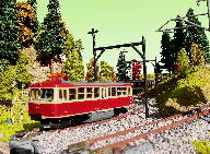
I mean really tight turns. Turns too tight for anything with long wheelbases, like heavyweights or streamlined pasengers, modern high-cube box cars, or double-stacks, and of course my Shinkansen trains, even when building the "alternate curve" corner. For giggles I built some alternate curve modules, and I have to say that it makes all but the shortest rolling stock look really toy-ish. In my case, a 500-series or 700-series coach hangs over so much (and the coupler/diaphragm unit is pulled to its limits) on such curves, that operation suffers. This shouldn't be taken as a criticism of T-Trak, by the way. Short wheelbase rolling stock and motive power works just fine on these modules, and things like trolleys or light rail look really quite good. Still, I'm exploring other—gentler—corner strategies more suited to what I'm looking to model...
Thus, Shelf-Top Modules
Okay, so T-Trak is cool, but not perfect (for what I want to model.) No big deal. It was just founded for a different purpose: fitting on one, maybe two, table tops. So rather than throwing away the baby with the bath water, I've formulated the following module specifications, which I'm modeling to, and I'm posting it here if you want to as well. These modules don't contradict the core tenets of the official T-Trak standard, but remain essentially compatible with it, so modules built to this standard should, for the most part, still conform to the official T-Trak standard.
So here are some basic tenets of the Shelf-Top Modules:
- Alternate track spacing - the T-Trak standard calls for two tracks, placed immediately next to each other (resulting in 25mm track centers.) But the standard also describes an "alternate" track spacing at a more normal 33mm center-to-center standard. This is good, because much of KATO's track (bridges, viaducts, crossovers, and more) are designed with 33mm centers. So all Shelf-Top Modules will be based on 33mm centers.
- Wider Curves - KATO recommends that their Shinkansen trainsets operate on no tighter than 383mm radius track. I'm currently experimenting with the KATO 718mm radius track to see if it can be used for both mainline tracks. Also, I'm not fond of the oddball 14⅜" size which limits the number of combinations possible. Creating non-rectangular layouts result in the possibility of gaps, stemming from the 14⅜" curve modules not fitting neatly into the standard 310mm (12⅛") grid. The Shelf-Top Modules introduce curve modules which are a multiple of the basic 310mm module grid size (say, a 620mm x 620mm "L" shape.) There are some issues with this, owing to limitations of KATO track lengths (you end up having to use lots of odd sized straights, or you have to hand-lay track.)
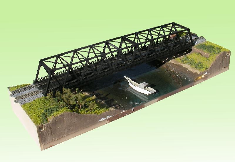
- No Backdrops - This is a bit of a twist, but one I think offers a lot of opportunity: there is no front or back to a module, allowing the module to be seen from either side. This is convenient, because transition modules (see hereafter) allow an otherwise "boring" straight double main-line track to meander back and forth; sometimes the track is in the foreground, sometimes in the background. Depending on what's next to it, a module might be seen from one side or the other, doubling the visual possibilities while on exhibit, at a meet, or on somebody's shelf. As a result, backdrops are separate units on stands that appear behind the string of modules.
- 310mm Grid - I've tried to constrain all module sizes to multiples of 310mm, including the curves. This allows for some very complicated layout shapes without the need for any special single-purpose modules, or odd sliver shapes, as is introduced when, say, a 14+ inch curve module is incorporated into a layout based on 12+ inch modules.
The idea is to make a module system in which most modules can still participate with T-Trak "constraints"—and so participate in ordinary T-Trak meets—but improve on some of the shortcomings that T-Trak presents to me.
About the Name
 |
| As evening sets, the Super Chief pulls into town. These T-Trak extensions are not just for modeling Japanese rail! |
What's in a name? Quite a lot, as I found out.
The original term I used was "Shinkansen Extensions". Unfortunately, when most people hear the term "Shinkansen" they think "bullet trains", and truth be told, I became interested in T-Trak because of the potential it had for me to run some trains I picked up in Japan. Strictly speaking, Shinkansen means "new trunk line". As Wikipedia points out, it refers just to the track, not the trains that run on it, which are technically "super express". But almost nobody—not even the meticulous Japanese—are diligent about the distinction. So yes, Shinkansen Extensions were to run bullet trains (among other things) but more importantly, they're a new bunch of standards to extend the opportunities for modeling and operations.
That said, I didn't mean to suggest, with a name like "Shinkansen extensions," that this is only for modelers of Japanese railroads—that's just what I'm doing. Still, several people have been confused by the name, so I felt it was better to jettison it in favor of Shelf-Top Modules.
If you're so inclined, feel free to use these ideas to model whatever you want: after all, you'll be putting the scenery onto your modules, and running whatever rolling stock you want! Just bear in mind that the more you vary from the basic T-Trak standards, the more you risk not being able to join in the fun at meets. If you expect to only use your modules at home, that's probably not a concern. On the other hand, if you think that part of the charm of these modules is linking up with others, well, you're probably best served to stick with tried and true T-Trak specifications. After all, when in Rome, do like a Roman. ;-)
Sections: 3
Shelf-Top Modules - Module Types
— Thomas M. Tuerke
Here are some module types, starting with the basic introduced by the official T-Trak site.
Sizes
- Narrow Single: 308mm x 210mm (12⅛" x 8¼"). This follows the basic T-Trak module size; it's mentioned here only for completeness. In all respects, this module should conform to the official T-Trak specification, in terms of width, depth, and height, plus track location (using Alternate 33mm spacing.)
- Narrow Double: 618mm x 210mm (24⁵/₁₆" x 8¼"). This is the equivalent of two single modules, but note that the math doesn't exactly add up (because of the overhangs.) The general rule for a module is (310mm x N) minus 2 mm (leaving about ¹/₃₂" overhang at each end.)
- Tight Corner: 365mm (14⅜") square (T-Trak calls this its Alternate Corner.) Good for tabletop operation, and tight shelf corners, but limits you to shorter wheelbases. (Long wheelbase rolling stock, like my Shinkansen Super-Express and longer passenger coaches won't work very well on this...) Also listed only to introduce the following module design. In all respects, this should conform to official T-Trak Alternate Corner specifications. It is not a multiple of a "unit square" in size, so using this size makes certain non-rectangular layouts difficult to make without a variety of dedicated oddball size modules.
- Tight Corner Wye: This is a 365mm (14⅜") square with a portion of a single attached at a 45 degree angle. This module, in combination with 3 Tight Corners, creates a loop end which permits the red track to loop back to the white track. A pair of of these, one at each end of a string of modules, and you have a dog-bone. As with the Tight Corner, above, this module is not a unit square in size.
- Full Single: 308mm (12⅛") square. A module that fills a complete 310mm "unit square." Essentially just a Narrow Single module, but with a few more inches of module in back.
- Full Double: 618mm x 308mm (24⁵/₁₆" x 12⅛"). A full-depth module that fills two adjacent "unit squares."
- Wider Corners: See below (I'm still working on this.)
Mnemonics
 |
| " White to the Inside " |
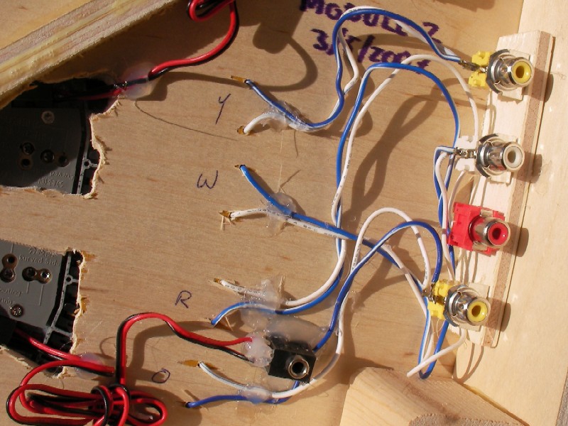
Official T-Trak establishes a simple mnemonic for wiring: Blue to the Outside. This is to remind you that, wiring using the KATO blue and white wire scheme, you should always wire the blue to the rail closer to the edge.
The Shelf-Top Modules standard takes a slightly different (but completely compatible) approach to this. It simply states White to the Inside.
This may seem obvious, even redundant, in view of the other rule, but the idea is for this mnemonic to apply to more circumstances than just KATO blue-and-white connections. Remembering this should help you remember much of the remaining Shelf-Top Module wiring standards.
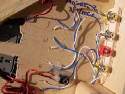 |
| Using color-coded RCA connectors for Shelf-Top Module wiring. |
For example, I've been experimenting with wiring, and couldn't find the connectors used by KATO. Examining an old video/stereo cable, I found the RCA jacks to be excellent for quick connections. The red and white pairing of stereo cables just begged to be used to service a double main line... hence "white on the inside."
From this, you can see:
- A Stereo cable is used to power a double main-line, with the white RCA jack connected to the inside track, (and red on the outside track.)
- The RCA connector consists of a center pin and an outer ring. The KATO blue track wire is connected to the outer ring, and the white track wire is connected to the inner pin.
From this, you can also see the following structure:
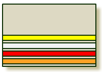 |
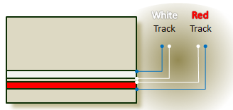
| Four Track Color Designations |
Track Designations
When the track consists of two main-line tracks, the track closer to the centerline of the module is the white track. The other track, closer to the edge, is the red track.
When the mainline has a "siding" or "trunk" line in front of the red track, it is referred to as the orange track.
When the mainline has a "siding" or "trunk" line behind the white track, it is referred to as the yellow track.
Module Types
- Standard: Single size, parallel track set at T-Trak's alternate straight locations. This is the basic module type, and despite its small size, is remarkably versatile. Excellent first module for newcomers.
- Double Standard: Double size, parallel track set at T-Trak's alternate straight locations.
- Siding End: Single size, #4 switches diverge from both sides; one end of the module is two-track, the other end is 4 track. Left Siding End refers to the module which would appear on the left side (when viewed with the track in the foreground) and Right Siding End otherwise.
- Siding: Single or, preferably double size, with 4 tracks, all on standard KATO 33mm (1⁵/₁₆") centers (the middle two—the main tracks—are at T-Trak alternate straight locations.
- Transition: Double size with 2 tracks transitioning from T-Trak alternate position on the front to alternate on the back. Left Transition is when the train enters the module and turns left, Right Transition is when the train turns right. These follow the design put forth by Paul E. Musselman in his double-wide alternate track spacing design.
- Mainline Grade: Single or Double size with 2 tracks climbing at 4 percent, which takes approximately 4 single or 2 double modules in all. The track can rise to the left or right, when seen with the track in the foreground. Mainline Grade sections are as follows: 1 raises the grade from 0 to 16mm through an easement, section 2 raises the grade from 16mm through 33mm, section 3 raises the grade from 33mm to 50mm, and section 4 raises the grade from 50mm to 66mm through an easement.
- Mainline Grade with Sidings: Tracks are in the same position as siding above, but the middle two tracks (white, red) are on a grade; the idea here is that the main line represents one trunk while the two sidings represent another, eventually one or the other will go off in another direction.
- Mainline with Climbing Trunk: Another 4-track configuration, but the yellow track climbs; the idea here is that the main line (red and white) will curve off once the yellow has reached sufficient height; thereafter, the orange and yellow converge to form new red and white lines beyond.
- White Grade: Red track is level, but white track is at a grade. Sections are the same as described above for Mainline Grade, but Level Sections are at a fixed level. For example, a White Grade Level Section 1 is with the white track 16mm above the red track, perhaps along a rugged coast where the two tracks could not be built parallel at the same grade.
Of course, people can build any sort of non-standard module, too, but that does limit one's ability to connect with others; generally, if you build a "non-standard" module, you should create book-end modules that snap to standard modules, so you don't have "loose ends". The idea is for everybody to have fun.
Pole Position
Trackside poles, such as for phone or telegraph are a regular feature along most rights of way. In electrified divisions, catenaries are similarly called for. In order to give adjacent modules an added sense of continuity, I'm recommending that such features be placed at six inch intervals starting three inches in from either end of the module. For practical reasons, it's recommended that these appear along the white track's side (clumsy hands are less likely to knock them over when they're behind the trains.)
For example, I'm modeling electrified Japan Rail, so I've made a point of placing catenary stands at six inch intervals starting three inches in from either end of the module. This means that the standard module has two catenary stands, and the double module has four. I've also placed four on the Tight Corner modules. This seems to produce good looking results.
Levels
Shelf-Top Modules also proposes a multi-level means of operation. Shelf-Top Modules puts elevated rail 66mm (~ 2⅝") above grade-level rail, and underground rail to be 66mm below (yes, through the interior of the module base.) Essentially, levels occur at intervals of 66mm.
I added this dimension to allow me to model true Shinkansen Super-Express trains on elevated tracks, as well as subway lines below. On a more practical, general-purpose front, it allows cross-over layouts and options for staging beneath or behind more complex layouts, a configuration which should have more wide appeal.
Sections: 2
Large-Radius Curve Modules
— Thomas M. Tuerke
As I said above, a minor drawback of the T-Trak system is its use of tight-radius turns. For some, that's not much of a drawback, but for what I'm trying to do, it really is.
| The Math They Said You'd Never Use |
| Take a moment to blow the dust off your high school geometry class notes, and you'll remember that old formula |
| c = 2πr |
| Translating that to English, it just says that the circumference of a circle is a bit more than six times its radius (remembering that π is about 3.14) |
| Now I'm not trying to evoke bad memories of boring lectures and dusty chalkboards, but that little equation is really useful here. Basically, it says if you want to make a circle—say, of track—larger by a certain amount—say 33mm—you need to add a bit more than six times that distance to the circumference. In other words, if you can add about 208mm of teensie straight sections throughout a full circle of track, it'll be about 33mm larger in radius. Some more math tells us that a 26mm bit of track every 45 degrees should do the trick. |
| The problem is that Kato doesn't make a 26mm track section (yet... Hey Kato: why not?) but it does make a 29mm section. So put two of those somewhere within your 90 degree turn, and whatever radius you were using, it's now about 33mm wider as a result. |
| That's the idea when I say that you can fake a larger radius using smaller radius track. |
| Now if only Kato made 26mm sections... ;-) |
Fortunately, Kato has larger radius curves, namely 481mm and 718mm, and these have some potential in curve modules. But we're not out of the woods yet. There are two problems using these bits of track (one of which is my own making...)
First of all, unlike the other (smaller) radii, both are one-of-a-kind: there is nothing 33mm on either side of either radius: no 448mm or 514mm, nor 685mm or 751mm. That means there's no off-the-shelf solution for parallel track. One way to work around this is to use the track to form the inner radius, and then fake a larger radius by inserting short 29mm straight sections every once in a while. Using this, you get a fairly reasonable approximation of 514mm (481+33mm) or 751mm (718+33mm.) See the sidebar at right for a bit more on that.
The second problem—the one of my own making—is that I'd like modules to be multiples of the basic 310mm module square. By doing so, you can avoid a lot of oddly sized special-purpose modules, since any corner module could serve as an inside or outside corner module... no single-taskers necessary. You just need a pair of full-width transition modules on either side.
Unfortunately, neither the 481mm and 718mm radius track will oblige this little need. For a 620mm double-length by double-length module, you would need an effective radius of 569mm (in 51mm from the edge of a 620mm square) for the outer (red) track, and 536mm for the inner (white) track.
As you might have noticed, both these radii are smack dab between 481mm and 718mm, which is too bad in one way—there's no simple solution—but being between has its upside: a combination of 718mm and 481mm pieces can make something pretty close to the desired 569 and 536mm curves. Even better, the curves have easements, which is a good thing. The bad part is that it requires a bit of track chopping to make, as one 718R15 gets cut in half to start and end the inner curve. Not terrible, but not something that's just going to snap together, either.
As a side note, I should say that it would be really easy to just use flex track to make whatever radius curve was required, but that would be cheating: I've been trying to keep these modules as close to snap-together as possible, just for overall simplicity. While I personally have no problems hand-laying track, not everybody thinks that's fun... ;-)
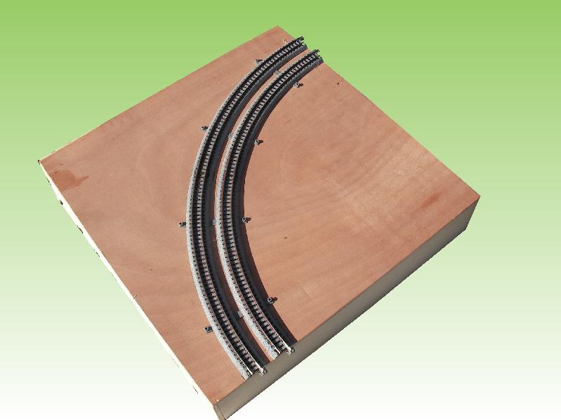
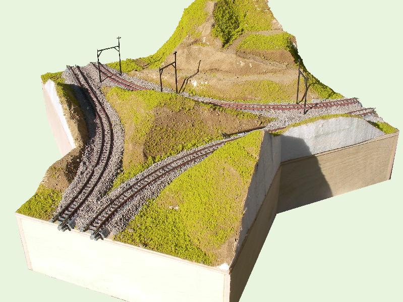
Here is a Measured Drawing of the thing. The track layout is still experimental (I have built one of these modules, but using flex track) so I don't swear by this specific configuration, but if somebody wants to make one, this is one way to do it.
Another way is to just rely on 481mm curves, and have straight track leading from the edge of the module to where the curve would begin, a distance of 88mm on either side of of each curve. You could cobble together something from the various short pieces, or get four expandable sections S78S. The down side here is that you don't get a continuous curve if you put two of modules together at the end of a table. And yeah, this may not be a down side to some. In fact, it has the upside of forcing a straight section between curves if you want to make an S curve with two adjacent curves.
But stay tuned for more...
Update: Use of RCA plugs
— Thomas M. Tuerke
Just a note of caution: The Australian T-Trak Guidelines (released about a year after this, circa March 2008) also follows the practice of using RCA stereo jacks for power distribution. Similar to what I describe above, they follow "white to the inside" for how individual connections are made (white wire to the inner pin, blue wire to the outer jacket) but unlike the mnemonic I mention above, they designate the white track to outside.
This isn't operationally terrible, in that if one finds oneself going down under, just plug red power cable to the white module jack, and white power cable to the red module jack, and things should work... but it's something to be aware of.
(Or make what I refer to as the "Australian Inverter" which does this for you... ;-] )
Module Building Tips
— Thomas M. Tuerke
This is just a short but growing list of tips for building the modules. More complete instructions are found at the official T-Trak site, and Paul E. Musselman's unofficial site has some other ideas on assembling modules, so I won't repeat them here.
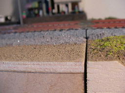
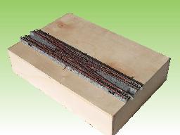
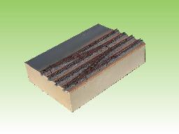
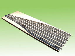
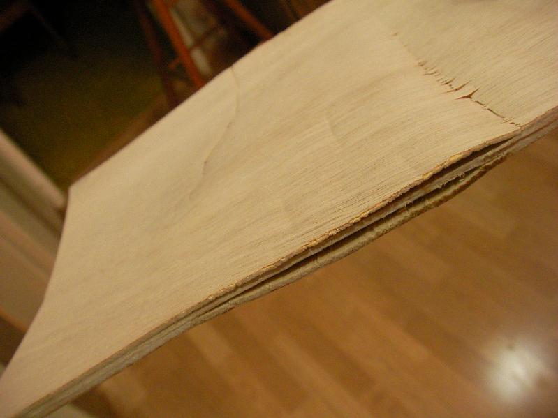
| Don't Skimp on the Base |
| I thought I could save a few bucks by getting a cheaper sheet of plywood, but it actually cost me more because I got fewer modules out of it. In the store, it looked reasonable (moreso than the photo below...) It had just a little warping that I thought would not be too bad considering the small pieces I was planning to cut down to. Big mistake. |
 |
| Turns out, the warping was hiding a multitude of sins below the surface, and they only became evident after I cut the sheet down to size. Lesson: don't think you're saving a few bucks with the cheapest line of wood. Almost half of the sheet was wasted, and the half that worked needed lots of bracing to keep from looking like a crumpled gum wrapper... ;-/ |
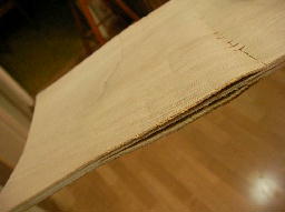
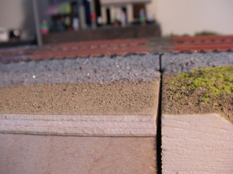
 |
| The good stuff is smooth and flat, and stays that way even after being cut. |
| PS: Too much headache? You can order pre-cut module pieces from N-Trak.org's online order form. I'm a DIY kinda guy, so I didn't try them, but they're there for you if you'd rather do that. |
Frame Construction
- When buying the ¼" plywood, be sure that it's flat. I bought a couple of sheets of cheap (in every sense of the word!) stuff that ended up warping and even delaminating, and that's not the stuff you want to make modules from. You may have to pay a few more bucks for the "good stuff" but you'll be happier in the end if your module isn't warped or bowed. Flat, Straight, and Square equals happy operation.
- The T-Trak site tells you to use T-nuts in the base blocks. These are great if you can get them, but I found that an ordinary hex nut works when pressed into a hole slightly smaller than the "major diagonal" of the hex nut. If you use standard "two-by" stock to make the base blocks, the wood is usually soft enough that once you've drilled a hole up into one end, you can press the nut into place by clamping the two parts into a vice and squeezing down. All my modules use this technique, usually with a drop of CA (Super-glue) to make sure it doesn't come out again.
- Paul Musselman's site claims that "Track height above the table top is 4 inches", whereas the official T-Trak site is unambiguous that you "Place these 2-3/4" high T-TRAK modules right on a table, for fast, easy set-up. Use leveling bolts only if needed." Lee Monaco-FitzGerald explains that "an early modeler chose to use NTRAK 4 inch leftover sides and the ensuing mix-up has caused others problems, especially at shows, since." For that reason, the Shelf-Top Modules conform to the official T-Trak standard (where rail height is about 3⅛ inches above tabletop: 2-¾" module height + approximately ⁵⁄₁₆" roadbed+rail height; that works out to a nice 80mm.) It's trivial to prop such a 2-¾" module to 4" when needed, but a wee bit more difficult to go the other way around.
- Depending on which website you visit, the length of the standard single-width module is either exactly 310mm, 308mm, or only 306mm long. To help in the fight to eliminate confusion, Shelf-Top Modules are built to th 308mm width because (a) that's the official T-Trak's 12⅛" measurement (coming in at a respectable 307.975mm, if you're going to split hairs,) (b) it allows some wiggle-room for less-than-perfect construction: about 2 mm—roughly ¹⁄₁₆"—between each module, but (c) isn't excessive. You can use 306mm for your module length if you're uncertain about how precise your work will be, but be prepared for somewhat larger ⅛" gaps between modules.
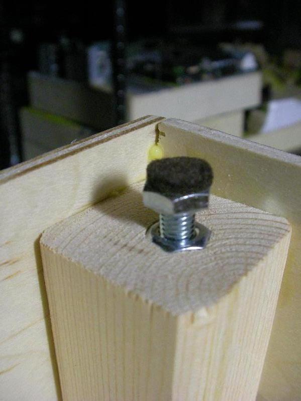
- I've made a point of putting adhesive-backed felt pads on all my leveling bolts. They're friendlier to my shelves and table tops, and tend to slip less in other circumstances.
With modules being 12⅛ inches (308mm) long, you get a reasonable amount of overhang to make sure nothing interferes with the joiners locking into place. Use 306mm as a length if you're not sure how square your work is, but be prepared for a much bigger gap. | 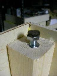
A felt pad on the bolt makes the module more table and shelf friendly (and it's less likely to wobble, too.) Also note that instead of a T-nut, I've just used a plain old hex nut pressed into a hole just small enough to make the nut fit very snugly. |
Track
- I've experimented with various adhesives to hold down the track, and have settled on these two choices: Hot glue and E-6000, (a rubber-type adhesive found in most craft stores.) The hot glue does an excellent job of placing the track quickly, and can be softened again with a hair dryer if minor repositioning is necessary. Hot glue generally holds the track fairly well, but if you are hard on your modules (that is, if you take them to meets, transport them often, or connect and disconnect them often) then a dab of E-6000 under the track ends when they come up holds them in place pretty much forever afterwards.
- When securing track, be absolutely sure no glue gets into the pockets where the joiners snap. Stray adhesive will either glue the existing joiner in place, or prevent the other joiner from clicking in place. The former is a problem if that joiner fails, the other just prevents the module from attaching to another module. (Fishing out glue before it's set is inconvenient, but picking it out once it's set is really tedious! Ask me how I know... ;-)
- I don't glue down my switches, but allow them to float; only the adjacent track is glued down. This way, if the switch ever goes bad, it's a matter of prying up that adjacent track and sliding in a new switch.
- I prefer to solder the joints of track, (doing this before applying scenery.) It's not necessary, and many other T-Trak builders have said their modules work fine without, but you do have to be very careful: if one of those internal rail joiners goes bad, trains won't run very well. I also find that the track is smoother this way, since the rail-heads can be aligned and kept level, regardless of the abuse the module may receive. If you don't solder, be very careful when applying scenery, ballast, and adhesive: capillary action will suck all that gunk and badness into the joints of the joiners if you allow it. (If you decide to solder afterwards, you'll have a devil of a time getting the joint clean, so expect to work at it... ;-)

- Most craft stores sell paint-in-a-pen applicators. I've found that two shades of brown applied to the sides of the rail take down that toy-train sheen and make the track look a bit more realistic. A bit of scrap wood pushed over the rail tops should clean off any stray paint. Of course, if you've got an airbrush and rust-colored paint, that works, too. Either way, if you do paint the sides of your rail, stay away from any joiners that aren't soldered.
Scenery
- My preference is to ballast last, after the surrounding base scenery has been applied. It supports the look that the world was there first, and the track came later (but then again, I'm modelling well-maintained Japanese right-of-way.) Old or infrequently-used right-of-way can be done in reverse order if you want the look that the wilderness has begun to reclaim the roadbed.
- Nearly any scenery technique that works for "big" layouts works for these modules, too. For fun, I've used insulation foam, plaster, even foam-core project board. If you use "messy" techniques, make sure you don't go over that "imaginary line" that extends up from the corners and edges of the module, so you don't interfere with the neighboring modules.
- I find that KATO's ballast blends better with the track than with the other brands I've used. Compare the photos of the standard single module vs the tight-corner wye, (both below) to see what I mean. As I get time, I'm going to replace the other stuff with KATO's ballast.
- When ballasting, I keep it to an absolute minimum around switches. Rather than pouring it on and spraying with matte medium or other liquid adhesive, I paint the area around switches with thinned white glue so I can control where it goes (and more importantly, where it doesn't go) and sprinkle the ballast over it. Track farther away gets the usual ballasting treatment... but I don't want anything to get into the switch mechanism.
Finishing Touches
- I've toyed around with putting strip velcro on the edge of my modules, and having short cloth skirts with the other part of velcro on them, just for looks.
- Another idea I've played with is appropriately-colored felt strips cut to the shape of a module edge. These should help lessen the visibility of gaps between modules. They wouldn't be permanently attached, but could be put in place if there's a particularly big gap between two modules.
- Similarly, putting finishing treatments on the ends of modules helps disguise scenery mismatches when two disparate modules are brought together. Such treatment above grade might depict rock cliff (even though it's flat and painted on) while the ends of a module base might depict a stone, concrete, or brick wall.
Travelling
I find that one's travel kit should contain these items at a minimum:
- Pliers, needlenose.
- Flat-head screwdriver. Not only for screwing down any loose terminals and such, it's also good for prying apart modules.
- Track cleaner of choice. There are two schools of thought: abrasive or chemical. You pick, but dirty track is not fun. ;-)
- Glue: CA (Super-glue,) E6000, hot-glue gun, whatever. Things break. You want to be able to fix them.
- Touchup paint... the color used for your scenery base (dirt, concrete, etc.) Same reason.
- Duct-tape. "It's like The Force: it has a dark side and a light side, and it holds the universe together."
My motto is AHAB, or Always Have A Backup; in addition to the usual, bring spares. Carry extras:
- KATO joiners, just in case a module loses or breaks one. These joiners are literally what hold everything together. ;-)
- Wire connectors and cables.
- An extension cord or two.
Modules
— Thomas M. Tuerke
Below are just some of the module variations I've built or am experimenting with, and I'm listing them here for your benefit; if there's something that seems interesting to you, feel free to build one yourself (and let me know how it works.)
Sections: 9
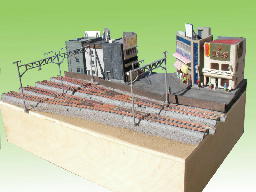
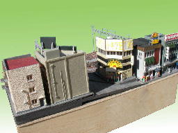
Module Facts: Narrow Single
— Thomas M. Tuerke
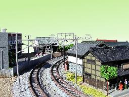
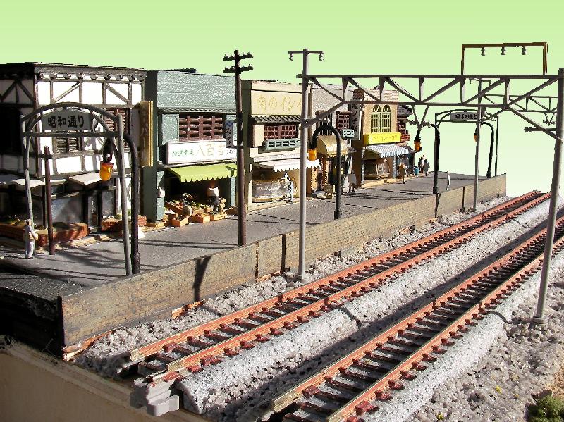
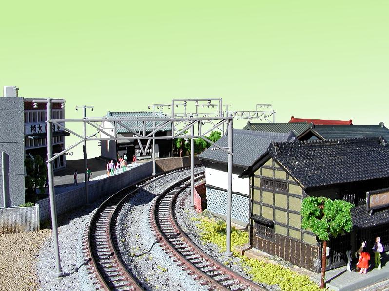
These modules, measuring 308mm x 210mm, are in all respects just standard T-Trak modules with alternate spacing track locations (that is, 33mm centers.) I've built several in my exploration. As you can see, despite their seemingly small size, they're remarkably versatile—and don't have to be boring.
Shown below are a few specimens (again, in varying degrees of completion.)
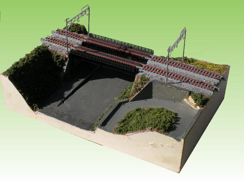
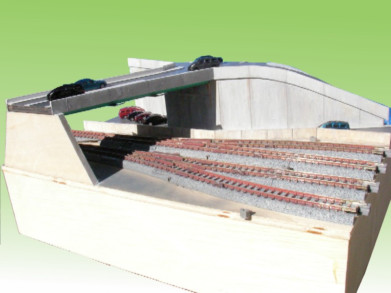
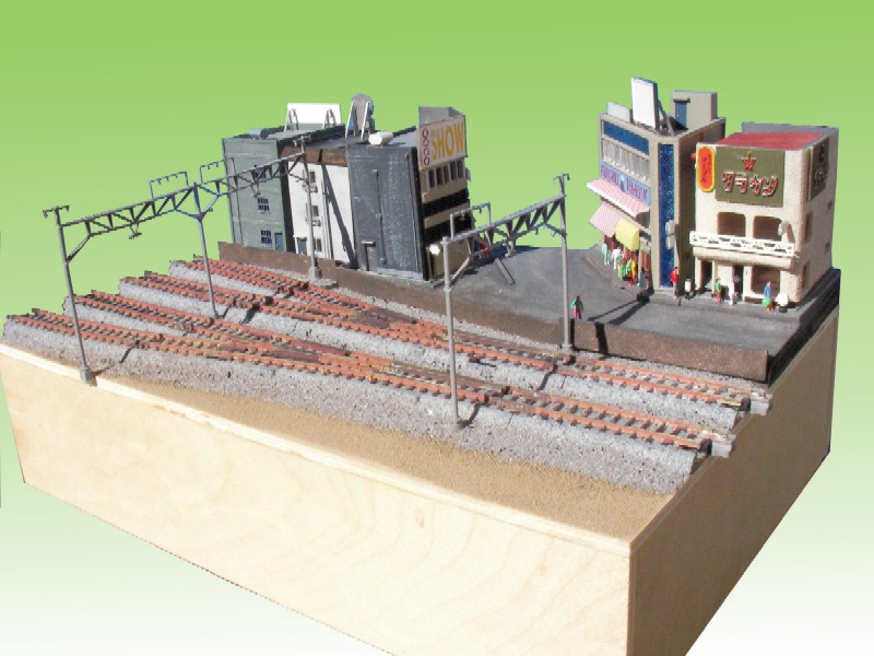
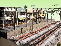 | 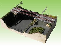 |
| Old-town district by the tracks | Early Scenery on the Highway Overcrossing |
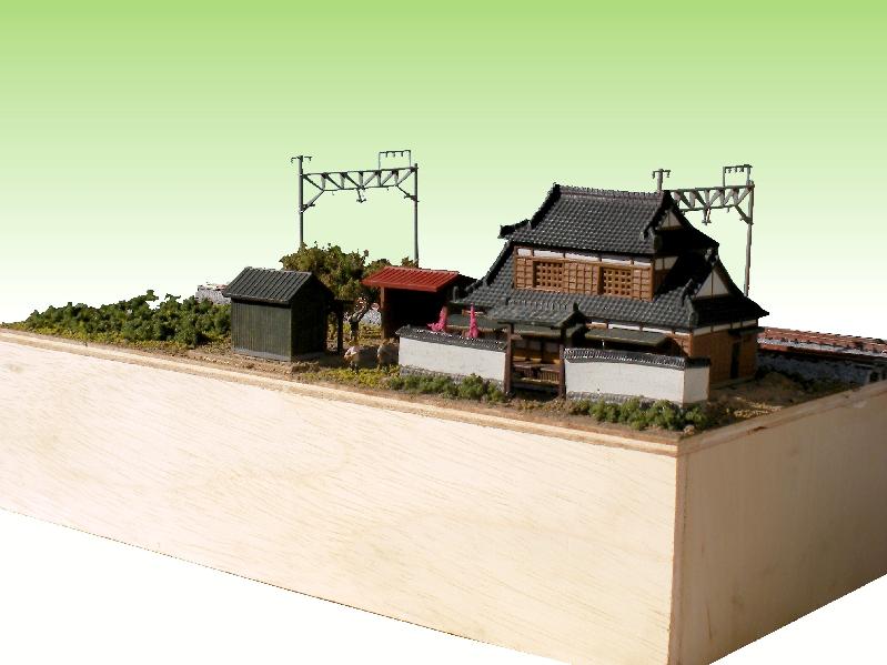
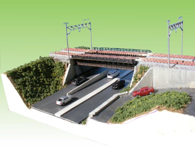
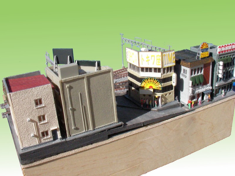
 | 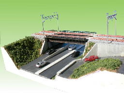 |
| Old farmhouse by the tracks | Highway Overcrossing with a bit more scenery |
Hopefully you see that there's quite a bit of scenic potential for something the size of an A4 sheet of paper. While there are bigger module sizes, you can have quite a bit of fun at this level.
One variant of the basic single module is to put a double-crossover on it. If the track plan would otherwise be two independent loops, this would allow you to move trains from one track to the other.
See the Measured Drawing.
Module Facts: Narrow Double
— Thomas M. Tuerke
The double just lengthens the single module size to double proportions. This is typically to model stations (with platforms on either side) or other scenic elements that don't lend themselves to a single module.
Here, too, are photos showing modules in varying degrees of completion.


Click to see a Measured Drawing.
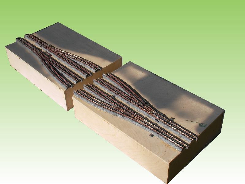
Module Facts: Siding End
— Thomas M. Tuerke
This module is typically a single, but comes in left or right varieties.
The determination of "left" or "right" is made based on which end of a siding the module would be placed, with the red track to the front.
 |  |
| Undecorated Left and Right Siding modules | Scenery on a Left Siding module |
 |  |
| Scenery on a Right Siding module | The other side of a Right Siding module |
Electrically, the yellow and orange tracks should be isolated from their respective mainline tracks (less important for DCC, I suppose, but nice for classic DC operation.)
Click to see a Measured Drawing of this module.
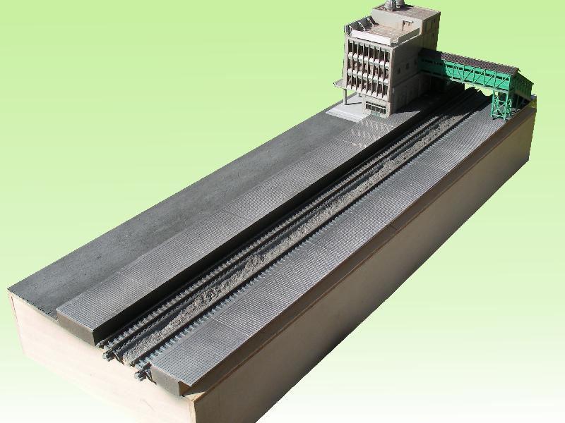
Module Facts: Siding
— Thomas M. Tuerke
Siding modules can be either single or double. Scenically, single modules can portray a small rural station for short trains (commuter consists, perhaps) or they can be simple extensions of longer stations, though the double siding is more likely.
I've built my station platforms to conform to KATO's, in that they are 9/16" above ground level (conveniently, this amounts to 1/16" styrene placed on 1/2" MDF.) Note that the front platform (next to the orange track) is really narrow, (unless the module extends outward in excess of the standard 1.5" from the red track.)
Variations of the single-length siding module are the left and right Lap Siding modules, where left and right is determined like the siding end definition, above.
 |
| A right lap-siding module |
A more expensive alternative to the lap siding is the double-crossover siding (that has to be the most expensive single-size module you can make! ;-)
Electrically, the two sides of each siding should be isolated, to facilitate isolating trains in various sidings in DC operation.
For a Measured Drawing of the lap-siding module variant.
Module Facts: Tight Corner
— Thomas M. Tuerke
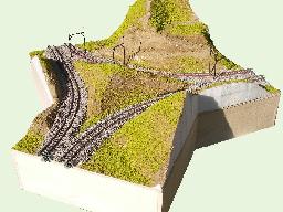
This is what basic T-Trak calls the "Alternate Corner", and produces a 90-degree turn at radii 315mm (red track) and 282mm (white track.) In building a few of these, it became clear that they're great for shorter wheelbase rolling stock, but they're too tight for longer wheelbases, such as Shinkansen or other full-length passenger coaches. Operationally, the length of the coaches mean the diaphragm/couplers are stressed to the limit, and visually, the angle between adjacent coaches just doesn't look right to me. As a result, I'm currently investigating what it would take to make larger curves, of the 481mm or 718mm variety, but that fit in multiples of the 310mm x 310mm grid that T-Trak and UniTrack essentially create.

Still, at only 14-plus inches square, another example that small spaces still allow rich scenic opportunities:
Click to see a Measured Drawing.
Module Facts: Tight Corner Wye
— Thomas M. Tuerke
This is a variation of the Tight Corner (above) and serves roughly the same purpose as T-Trak's Junction Module, but in a more economical space. It consists of a regular Tight Corner module with a portion of a standard single module attached at 45 degrees to one corner.
 |
| Scenic options on a Tight-Corner Wye |
It does have the effect of setting the modules on one side of the wye at a 45-degree rotation with respect to the other side, but this also presents some interesting opportunities. A second wye will cancel out the rotation.
Six Tight Corners and two Tight Corner Wyes allow you to create a "dog-bone" layout with loops at the ends. In this case, the white track on modules inserted between the two loops just becomes the return portion of the red track. As with the Junction Module description on the T-Trak page, any number of these modules can be used to create interesting shapes (but with the problems with a 14 inch module integating into a 12-inch gridwork, as always.)
Some possibilities include:
- The conventional dogbone: three tight corners and one tight wye form a loop. The white track is an isolated loop, and may or may not have anything running on it.
- The extended dogbone: two or more straight modules are included into the loop, making it more oblong. Switchwork such as a double-crossover may connect the red and white tracks.
- Joined loops. Two otherwise complete tracks are joined at the corners with a wye. The red track traverses the outside of the entire layout, while the white track merely runs around the local loop.
As you can see, there's quite some potential with this module type.
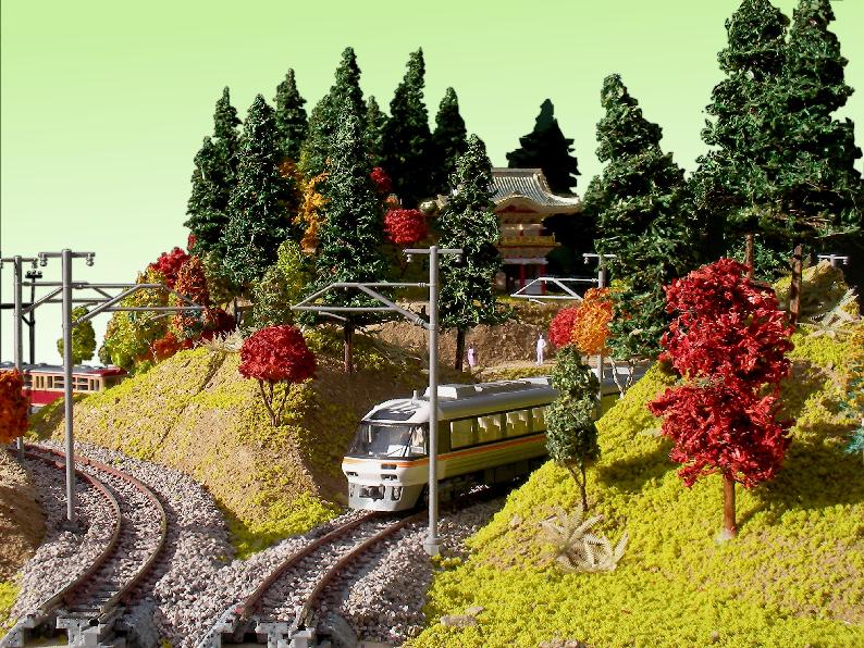
Coming in at slightly more that one square foot, this module obviously offers lots of scenic opportunity, too.
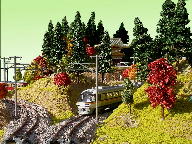 |  |
| The Hida "Wide View" Express rounds the bend | A diesel bus trundles back to town |
Click to see a Measured Drawing.
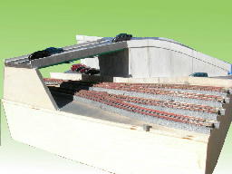
Module Facts: Transition
— Thomas M. Tuerke
The transition module is a means of transitioning the track from the front of the module edge to the back. This allows you to add some variety to the track; you can put any number of ordinary modules between the transitions, so that they're viewed from the reverse side. For this reason, modules don't have a front and back, and therefore don't include backdrops: (hint: create your modules to look good from both sides!) This module is designed by Paul E. Musselman.
Note that this does have the effect of reversing the definition of "red" and "white" tracks: for the duration of the transition, red is white and vice versa.
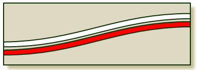 |
| A Left (above) and Right (below) Transition module |
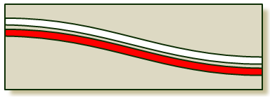 |
As previously stated, left and right are defined by the direction the train turns when heading into the module (and thus, what end of the transition they'd appear, assuming that the red track is normally in the foreground.)
Click to see a Measured Drawing.
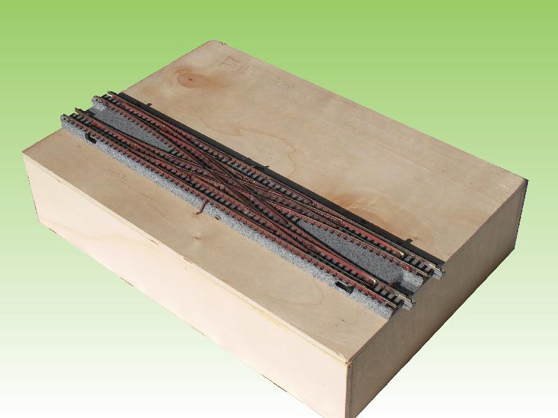
Module Facts: Narrow Yard Lead
— Thomas M. Tuerke
 |
| Undecorated Yard Throat |
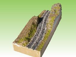
This is a variation I built a while back to serve two purposes, depending on where I put it on the layout. (That's also a cool point about these tiny module sizes: rearranging the layout on a whim.) In one instance, it's a terminus at the end of a point-to-whatever line. In another instance, it's used for staging, with the yard connected to the main track via a trunk that descends to "subway" level. I usually have the double crossover nearby, to allow arriving and departing trains to go from/to any track.
Because I use this module on two different levels, I've built this on MDF so it will sit at 66mm below nominal module track height. But I've also built a platform that it rests on to be elevated to "normal" track height when used as a normal module.
For DC operation, each track is electrically isolated from the others, as well as the lead tracks. (And as always, for DCC operation, it's a moot point, but it's trivial to just feed district power to all six tracks and the two leads.)
Since full Shinkansen consists are quite long (typically 16 cars) my yard lead module connects to three or four six-track yard modules. I've not yet built a right end yard throat module, but doing so would allow double-ended yard operations.
Click to see a Measured Drawing.
Modules Tips: Tight Corner Junction
— Thomas M. Tuerke
This is a module design I've been deliberating how to implement. Way up above, I mention the "Mainline Grade with Sidings" and "Mainline with Climbing Trunk" module types, both being four-track configurations with the idea that two tracks go in one direction, and two go in another.
While I haven't built such a module yet, this is how I imagined the two routes to go their separate ways (at least on a Tight Corner; doing so on my proposed medium and/or wider corners would be similar, and made simpler by virtue of the fact that those are multiples of 310mm.) For example:
- The red and white tracks climb to +66mm, turn at +66mm and then descend. This requires a pair of "Mainline Grade with Sidings" style modules on either side.
- The yellow track climbs to +66mm, crosses over the red and white tracks, which curve at grade, then descends as the white track. This requires a "Mainline with Climbing Trunk" style module, plus a two-track set of modules where the white track descends back to grade.
- A thought I've been entertaining is that red and white descend to -33mm while yellow ascends to +33mm (or vice versa.) The orange track stays at grade. The idea here is that instead of two double modules where only one track is doing grade changes, we can split the grade over both the main and trunk lines, and thus fit everything on one double module. Instead of needing a cluster of five modules, I could get away with four.
The short of it is that the red and white tracks form the curve, while the yellow and orange tracks go straight.
Click to see a Measured Drawing. Note that the drawing doesn't specify elevations; that's to be decided based on what other modules are used around it.


 Generate a QR code link to this page